- Published on
Diagram as code
- Authors

- Name
- Amit Bisht
Introduction
Historically, whenever I used to discuss any existing architecture with an engineer, their architecture diagram would never be in sync with the current state. It is a cumbersome process to build and they have low maintainability. Thus, wouldn't it be better if we could write code for it?
We are creating infrastructure with code, and it is working amazingly! So why not diagrams? Through code, we could gain all the collaborative features through Git.
There are multiple libraries out there which provide us with the capability. So, I am going to look into one of the popular ones, diagrams, which currently has 34 thousand stars. It supports all major cloud providers, Kubernetes, flow charts, saas products, custom icons, etc. Documentation is also available here.
Setup
I did not want to install a bunch of packages on my host machine, so I ended up creating a Dockerfile which runs through a Compose file with a source directory attached to the container as a bind mount. Since image generation is not always an ongoing process, every time we run docker compose up, it runs our code, generates the file then the container stops. The generated diagram file is visible to us in our file system through the bind mount.
Here is the source code of the setup.
FROM python:3.9.19
WORKDIR app
RUN apt update && apt install graphviz -y
RUN pip install diagrams
version: "3.8"
services:
diagrambuilder:
    build: .
    volumes:
    - ./src:/app
    command: ["python","/app/diagram.py"]
Usage
Let's first write a simple file and generate some diagrams.
from diagrams import Diagram
from diagrams.aws.compute import EC2
from diagrams.aws.mobile import APIGateway

with Diagram("Simple Diagram",show=False):
    c1 = EC2("web")
    api = APIGateway("API Gateway")

    api >> c1
Now run docker compose up, and you will see a new image generated in the src folder of the project.
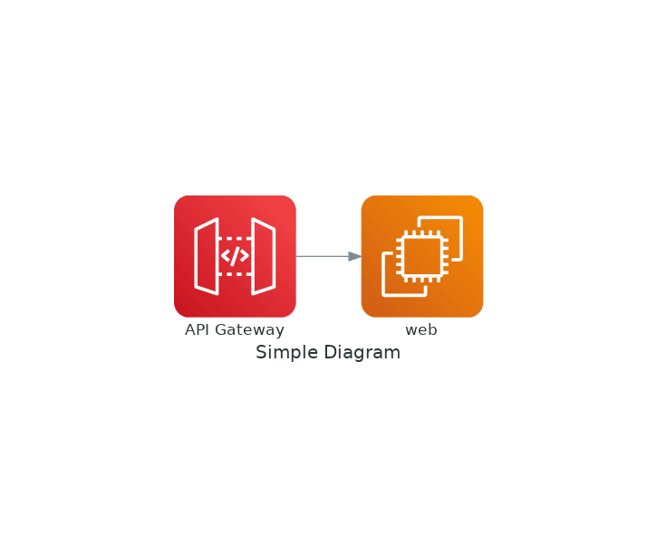
So, we import all the functionality from the Python diagram package. We are using the AWS modules to import nodes (such as EC2, API Gateway) to display stuff.
There are four building blocks.
- Diagram: In the global diagram context, global configuration is done at this level, such as diagram image format, size, etc.
- Nodes: These are the objects that actually display a system component, like EC2, API Gateway in the above example.
- Clusters: They are used to group multiple nodes together, such as multiple EC2 instances in a VPC.
- Edges: These are the edges between nodes. They can be bidirectional and dotted if required.
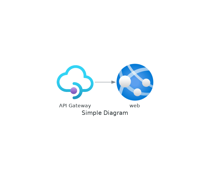
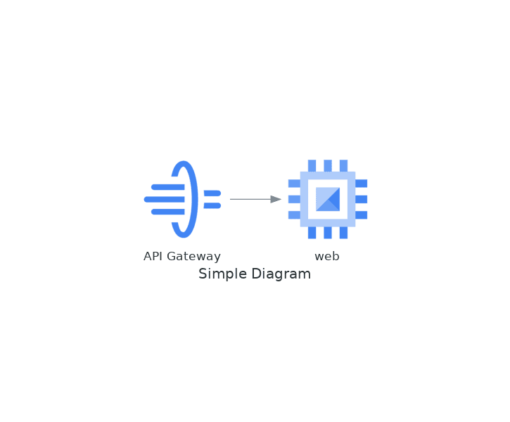
Let's create the same diagram on Azure and Google Cloud.
from diagrams import Diagram
from diagrams.azure.compute import AppServices
from diagrams.azure.integration import APIManagement

with Diagram("Simple Diagram",show=False):
    c1 = AppServices("web")
    api = APIManagement("API Gateway")

    api >> c1
from diagrams import Diagram
from diagrams.gcp.compute import ComputeEngine
from diagrams.gcp.api import APIGateway

with Diagram("Simple Diagram",show=False):
    c1 = ComputeEngine("web")
    api = APIGateway("API Gateway")

    api >> c1
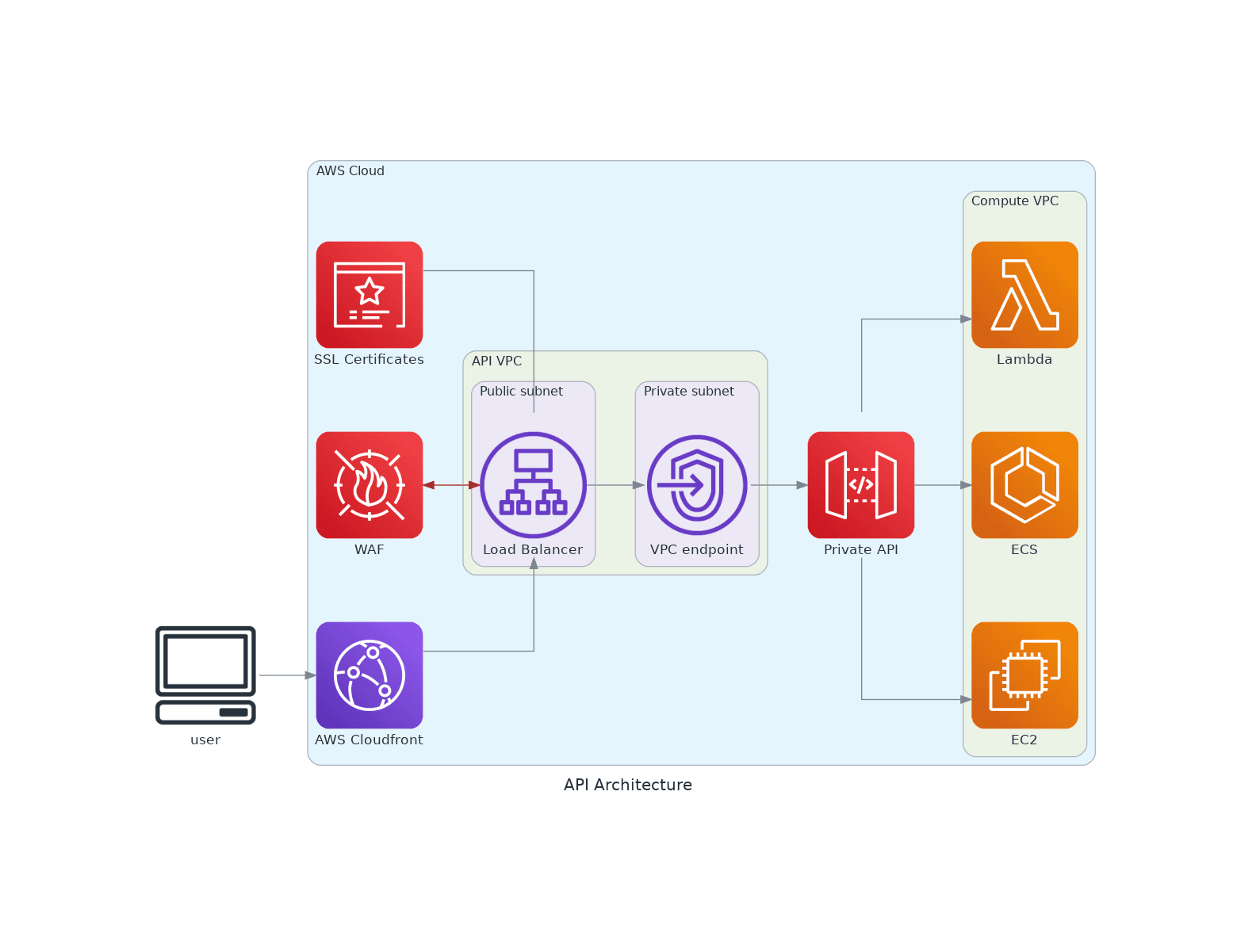
Now, let's create a new diagram that will utilize all the concepts.
# diagram.py
from diagrams import Cluster, Diagram, Edge
from diagrams.aws.compute import EC2
from diagrams.aws.database import RDS
from diagrams.aws.network import ELB, CF, ALB, Endpoint
from diagrams.aws.mobile import APIGateway
from diagrams.aws.compute import Lambda, ECS ,EC2
from diagrams.aws.security import WAF, ACM
from diagrams.aws.general import Client

with Diagram("API Architecture", show=False, direction="LR"):
    Client = Client("user")
    with Cluster("AWS Cloud"):
        cf = CF("AWS Cloudfront")
        acm = ACM("SSL Certificates")
        waf=WAF("WAF")
        with Cluster("API VPC"):
            with Cluster("Public subnet"):
                alb = acm - ALB("Load Balancer")
                alb = waf >> Edge(color="brown") << alb
            with Cluster("Private subnet"):
                endp = Endpoint("VPC endpoint")
        api = APIGateway("Private API")
        with Cluster("Compute VPC"):
            handlers = [Lambda("Lambda"),ECS("ECS"),EC2("EC2")]

        Client >> cf >> alb >> endp >> api >> handlers
This is the diagram that gets generated.
This package may not be able to generate all types of diagrams, but you can find some other tools that are available for very specific cases. There are multiple options available to make your life easier.
Thanks for reading!